
The first in several videos outlining my progress. This very shaky video shows driving around the bot in early test stages.
Bluetooth streaming video at 7-11fps on Android

I have been neglecting this webpage quite a bit, but that does not mean I have not been making progress ! I’ve actually made huge progress after discovering some issues with the pin configuration on the stm32 “open407” board I was using. Turns out some of the pins were mapped to a int on one of the integrated IC’s on the discovery board itself. So I never could have gotten jpeg or correct raw images. This explained why my images were always off and distorted.Sorry for not updating and keeping track of everything on the website. I have found that the upkeep of the website, twitter feed and facebook page is quite a bit of work that I would rather spend on the code at this point. Once I have more exciting info and neat pictures then I think I should focus more on the social media aspect.
That said if you like this project please friend Zonerobotics and like us on Facebook. I will update that page the most.
https://www.facebook.com/Zonerobotics
Summary of whats been completed:
- Jpeg compression via the ov2640 camera
- Streaming output of camera data through bluetooth giving optimal throughput
- Java base code updated and working with streaming protocol
- Java base code has stubs and plans to open to GPB so we can support other languages
- Java base code implemented in android and simple client made
- Gpio read handling tested and validated in Android client
- ADC read tested and validated
- GPIO write, PWM (motor control) write and other commands implemented
- Joystick module implemented that converts XY into power for motors to give extreme control and sensitivity (Although my gui does not have a “joystick yet”)
So there’s a lot getting done, and the more that gets done the more there seems to do. I’ve also thought of a way to keep the base design modular and cheap. This is just a quick sketch of what I’m going for and nothing is set in stone till I’ve tried it and seen how it works. I know I left out some stuff, but hopefully you get the general idea.

TODO
I really like the rapid prototype model. So there is a lot of building and testing to do. Then there is still the circuit design, body design, motor selection etc, etc. I’m going to hopefully release the first workable solution that actually uses the stm32f4 discovery board, this way it will be big but it will be cheap and come with lots of extra components such as the accelerometer, speaker etc. So I really want to hold off on circuit design till I’ve added drivers for the pieces of the stm32f4 discovery components and decided which ones to import into my circuit design.
Like I said if you are interested please friend us on Facebook and like the project, tell your friends about it and if you want to volunteer your time let me know via Facebook.
Raspberry pi setting up model A with camera module as bot.
Using my model B with a usb video camera was fun but with the new camera module and the cheaper model A I wanted to give those a go.
Parts:
rPi model A (no ethernet, one usb) $25
Camera Module for rPi $25
RTL8188cus wifi dongle (<$5)
Something to drive around
Circuitry to drive motors
Circuitry to tell you when batteries are low http://zonerobotics.com/wordpress/?p=257
Connect Over Serial:
To do this I used a usb<->uart converter plugged directly into the rPi as the pinout describes here http://elinux.org/RPi_Low-level_peripherals. Using 115k, 8n1 and a putty session.
Connect wifi:
http://learn.adafruit.com/adafruits-raspberry-pi-lesson-3-network-setup/setting-up-wifi-with-occidentalis
Update rPi, setup Camera files:
http://www.tweaktown.com/guides/5617/raspberry-pi-camera-module-review-and-tutorial-guide/index2.html
Free up some space (I’m on a 2 gig sd)
This will ruin X11/gui interface. You might want a bigger sd if you still need that, I dont want it for now.
sudo apt-get remove `sudo dpkg --get-selections | grep -v "deinstall" | grep x11 | sed s/install//`After that I have about 400 megs left 🙁 not much to play with.If you want to take off more here is an article http://www.cnx-software.com/2012/07/31/84-mb-minimal-raspbian-armhf-image-for-raspberry-pi/
Streaming from the Camera Module:
Looking around I see no /dev/video0. So upon looking through the vast internet I dont think there is a video4linux driver. How lame, I thought this would be plug and play. I’ve written my own cmos camera drivers and broadcast them through bluetooth with the stm32 it’s not trivial. I was hoping for a simpler solution being that this camera was expensive and that the pi is a powerhouse compared to my other units. See this article for more details about why it does not work and some ways that it might
http://raspberrypi.stackexchange.com/questions/7446/how-can-i-stream-h264-video-from-raspberry-camera-module-via-apache-nginx-for-re
This page has a more optimistic output with three different ways to stream.
http://www.mybigideas.co.uk/RPi/RPiCamera/
First thing I had to install VLC, ouch 132mb gone. Then I tried
raspivid -o - -t 9999999 |cvlc -vvv stream:///dev/stdin --sout '#rtp{sdp=rtsp://:8554/}' :demux=h264
The latency was really bad, seemed like minutes till I actually got the video. It kept restarting over and over and hitting this error
[0xd01d28] main input error: ES_OUT_SET_(GROUP_)PCR  is called too late (pts_delay increased to 1953 ms)
[0xd01d28] main input error: ES_OUT_RESET_PCR called
So I found this link that talks about “low latency” gstreamer and I was using gstreamer on my linux box the other day with much interest so I was pulled more to this.
Before installing gstreamer I deleted more stuff with apt-get remove as in the above article. Left me with about 300mb, I didnt uninstall vlc since it was the only thing I have going so far. Gstreamer was 154mb, these packages are huge. Here goes another 20 minutes waiting for that.
Fought with this for a while, I could never get a client to work with gstreamer. Tried vlc again with slower/smaller settings and it was just as crappy.
VLC Sorta Success:
After working with these tools for a long time I got this to work pretty well. Its smooth fast and no freezing
raspivid -t 999999 -h 600 -w 800 -fps 30 -hf -b 2000000 -o - |cvlc -vvv stream:///dev/stdin --sout '#standard{access=http,mux=ts,dst=:8080}' :demux=h264
I tried to make it smaller and less framerate/size/bitrate each time it got worse and worse. With a smaller bitrate/fps it would freeze and disconnect, which does not make any sense to me, with less data it should work better right ? But I think it has to do more processing if you scale it in any way which hogs up the cpu and screws everything up. I read tons of articles the last one was this
http://www.raspberrypi.org/phpBB3/viewtopic.php?f=43&t=43969
Making Webpage:
Installed apache then used this on a video.html page
<!DOCTYPE html>
<html><body>
<OBJECT classid="clsid:9BE31822-FDAD-461B-AD51-BE1D1C159921"
 codebase="http://downloads.videolan.org/pub/videolan/vlc/latest/win32/axvlc.cab"
 width="800" height="600" id="vlc" events="True">
 <param name="Src" value="http://PI_IP_ADDRESS:8080/" />
 <param name="ShowDisplay" value="True" />
 <param name="AutoLoop" value="False" />
 <param name="AutoPlay" value="True" />
 <embed id="vlcEmb" type="application/x-google-vlc-plugin" version="VideoLAN.VLCPlugin.2" autoplay="yes" loop="no" width="640" height="480"
 target="http://PI_IP_ADDRESS:8080/" ></embed>
</OBJECT>
</html></body>
Latency !!:
I’m getting like 4sec of latency which ruins everything. I had much better results with the usb cam. However these people seem to think it will work much faster with “no latency” so I’m going to try their netcat solution later
http://www.raspberrypi.org/phpBB3/viewtopic.php?f=43&t=39996&start=50#p341674
Yes at least 3 second delay. No change in delay with bitrate. Looking at the nc solution this is the most complete example I can find (first line run on pi, second on windows)
raspivid -t 999999 -o - | nc 192.168.1.76 5001
c:appsncnc.exe -L -p 5001 | c:appsmplayermplayer.exe -fps 31 -cache 1024 -
My exact example was
On the Pi:
raspivid -t 999999 -vf -hf -b 2000000 -o - | nc 192.168.2.17 5001
Then on the machine (where I had to download mplayer and all the codecs)
raspivid -t 999999 -vf -hf -b 2000000 -o - | nc 192.168.2.17 5001
This would start off just like the rest but after about a minute of running the latency was gone. There is maybe a 200-300ms latency. I could snap my fingers and see it way before I could say “one Mississippi” (very scientific).
Conclusion:
I don’t get it. I read online about all these “it does not have enough power” etc. etc. My stm32 could pump data out via the DMA as fast as we could process it.
- Video is shaky, camera is stable but it looks like what you are looking at is in a earthquake
- Motion is frequently blurred and pixelated, smearing across the screen
- Camera is much more expensive than a usb solution
- All normal ways of streaming have a 3+ second latency, some other methods have less latency (netcat) but they are not reliable and seem to crash all the sudden. Plus they are not streaming into a webpage or anything simple.
- reducing bitrate or resolution just seems to make things worse
If I have to choose between this and a simple usb camera I was having lots more luck with usb camera. I can see the application of the raspberry pi camera in maybe a webcam or something that takes pictures, but as eyes for a teleop bot the usb camera may not be as HQ but it also did not smear, shake, lag or cost as much !
STM32 code revision
Thinking about this for a long time I’ve decided to re-factor all of my stm32 code to make it more versatile. I need to be able to turn on/off peripherals at will and set them on a schedule. The current system is very static.
So I’ve devised a way to use nodes and serve them up and configure them at will based on the server. This helps a lot with configuration and should help me put an easy configuration face onto any stm32.
I’m still torn between the PI and my hardware. I think I could add my current hardware to the PI and get really good expand ability + camera on the raspberry pi; however, I want to make sure the users are able to configure and tweak all of the settings through their pi rather then just get a video stream.
Goals:
Hardware Comm agnostic(can switch from usart to spi etc)
All perph have standard
One state machine, schedules
Will work well with Pi
each perph has its own commands
Protocol:
Encapsulated, multiple commands at once inside
ID:TotalSize:[ID:Size:Data …. n …. ID:Size:Data]CRC
The outer “ID” is the id of the server or hardware, the inner “ID” is the id of the command that will handle “Size” amount of data. The data is as such
CMD:Data
so for example a “update schedule (0x01?)” command that sends data 0xFF will cause the perph to fire on every interval of the state machine. Commands that span perphs will start with 0 commands that are custom will start at 0xFF down. So for instance a command that sends video config data will start from the upper range, and a 0xFF will mean different things to different perphs.
Actually I think we could get away with no overall size and just have a identifier followed by data. On the client side we reset on the id and continually calculate crc till we have a match.
rPi low voltage supervisor, let me know before batteries die
Goal:
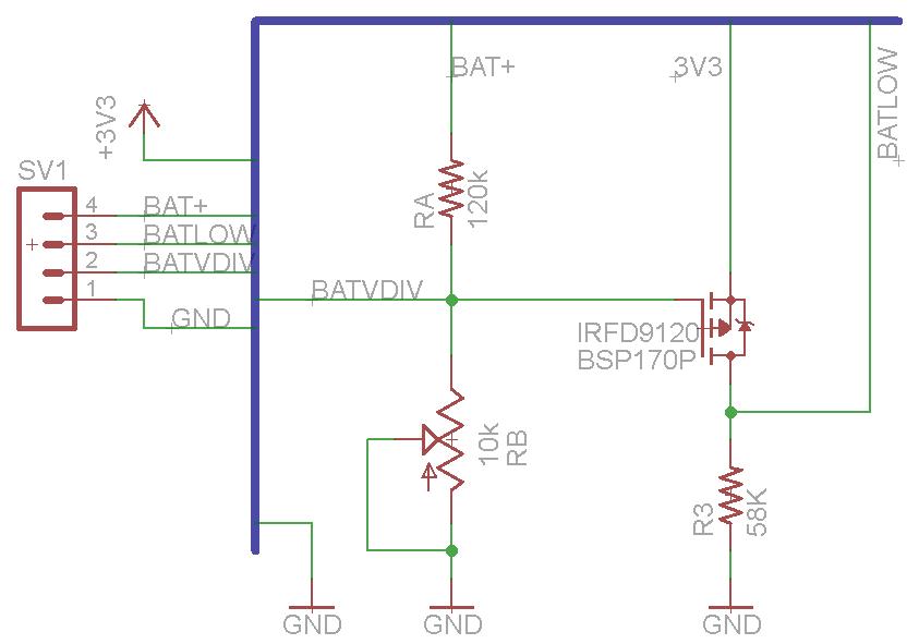
Know when the batteries voltage decrease to 7.0v because after that they cannot support the 7805 and decline rapidly. If we are moving and the batteries stop supplying enough current to the 7805 then the pi will stop responding and remain in whatever state it was in. So if we were going forward we will run into a wall and not stop. I want to make sure I know if the batteries are low and then at least I can stop controlling the unit!
How I did it:
I used a P-Chan Mosfet, pull down and a voltage divider. The voltage divider takes the voltage right from the battery pack. So when the batteries get to 7v the voltage divider outputs about .538v. I was using the IRFD9120 because its all I had laying around (it is actually a poor choice for this circuit because its expensive!). The IRFD9120 has a Vgs(th) from -2v to -4v. It does not seem to be full “on” until I hit about 2.8v. My source to the mosfet is 3.3v coming out of the pi itself so to hit its threshold I need 3.3-2.8=.5v on the gate or less before it opens. The voltage divider is Ra=120k Rb=10k giving .0769 and .0769*7v = 0.538v giving the desired threshold.

Does it work ?
Yes it works pretty well. I’m using two CR123 rechargables and I get about 30 minutes before they start to drop. This circuit will let you know just as they start to drop off. From there you might still have another 5 minutes. I’m going to make the javascript in my control page turn all of the gpio off and disable the buttons when this gets triggered, along with logging the time. This way I will see how much time you have after you get notified.
| Run | Time | Battery V | ra | rb | vout | LowOn | State |
| 1 | 8:17 | 7.97 | 120000 | 10000 | 0.613077 | FALSE | |
| 1 | 8:18 | 7.76 | 120000 | 10000 | 0.596923 | FALSE | |
| 1 | 8:22 | 7.4 | 120000 | 10000 | 0.569231 | FALSE | |
| 1 | 8:26 | 7.3 | 120000 | 10000 | 0.561538 | FALSE | |
| 1 | 8:27 | 7.27 | 120000 | 10000 | 0.559231 | FALSE | |
| 1 | 8:29 | 7.22 | 120000 | 10000 | 0.555385 | FALSE | |
| 1 | 8:32 | 7.18 | 120000 | 10000 | 0.552308 | FALSE | |
| 1 | 8:37 | 6.83 | 120000 | 10000 | 0.525385 | TRUE | |
| End | 20min | ||||||
| 2 | 11:30 | 8.39 | 120000 | 10000 | 0.645385 | FALSE | Off |
| 2 | 11:30 | 7.91 | 120000 | 10000 | 0.608462 | FALSE | Working |
| 2 | 11:31 | 7.78 | 120000 | 10000 | 0.598462 | FALSE | Working |
| 2 | 11:34 | 7.56 | 120000 | 10000 | 0.581538 | FALSE | Working |
| 2 | 11:37 | 7.5 | 120000 | 10000 | 0.576923 | FALSE | Working |
| 2 | 11:44 | 7.48 | 120000 | 10000 | 0.575385 | FALSE | Working |
| 2 | 10:48 | 7.37 | 120000 | 10000 | 0.566923 | FALSE | Working |
| 2 | 11:49 | 7.31 | 120000 | 10000 | 0.562308 | FALSE | Working |
| 2 | 11:52 | 7.21 | 120000 | 10000 | 0.554615 | FALSE | Working |
| 2 | 11:57 | 7.1 | 120000 | 10000 | 0.546154 | TRUE | Working |
| 2 | 11:59 | 7 | 120000 | 10000 | 0.538462 | TRUE | Working |
| 2 | 12:00 | 6.92 | 120000 | 10000 | 0.532308 | TRUE | Working |
| 2 | 12:01 | 6.85 | 120000 | 10000 | 0.526923 | TRUE | Working |
| 2 | 12:02 | 6.52 | 120000 | 10000 | 0.501538 | TRUE | Issues |
| 2 | 12:04 | 5.35 | 120000 | 10000 | 0.411538 | TRUE | Broke |
| 2 | 12:05 | 6.44 | 120000 | 10000 | 0.495385 | TRUE | Off |
| 2 | 12:06 | 6.65 | 120000 | 10000 | 0.511538 | TRUE | Off |
| End | 30min |
Problems:
The 3.3 volts I get are from the pi’s 3.3v output so when the pi eventually does loose power because the 7805 can no longer function the 3.3v disappears. This means the output of the circuit is unknown. But I dont think it really matters at that point because the feedback into the rPi is pointless if its not running. So be sure to do your house keeping first and then ignore its output later.
The P-Channel Mosfet is really not for this application and costs about $1 each. I should get a cheaper mosfet since I’m not driving anything through it. There are some on mouser that cost about 7c such as PMV160UP,215 there are also IC voltage detectors but none of them seem to work right at 7v, and if I need to put in a voltage divider anyway I could just use a mosfet.
Todo:
Find Cheaper Mosfet, rebuild voltage divider for that mosfet.
Raspberry Pi + Wifi Dongle + Usb Webcam = remote control web bot
I will try and explain all of the steps that I went through to do this. Since I’ve already done it I might miss a few. Feel free to add comments and I’ll respond and or update the post. I’m not going to rewrite all of the instructions in other pages I will just link to them.
Setup Your Raspberry Pi
OS
Assuming you have some debian based version of linux running on your raspberry pi. I had a version of the os compiled with ROS included because I plan on using ROS asap. I got my version from here.
http://www.instructables.com/id/Raspberry-Pi-and-ROS-Robotic-Operating-System/
Direct Download Link of Image (Raspian)
Connection
Please use a ssh client and ethernet to setup the initial connection, or if you already have wifi setup all the better. I’ll assume your talking to your device through ethernet for now.
WebCam
Plug in your webcam to your usb port. Then run command “lsusb” hopefully you see a new device there, if not you need to search the net on getting your camera to work. Most of the information related to ubuntu or debian is still relevant and I find myself finding lots of solutions in posts that are not Pi specific.
If you do have a new device look at the ID, check the list of supported/verified devices here http://elinux.org/RPi_VerifiedPeripherals if its not there you might be out of luck but try anyway.
The application I used was mjpg_streamer. Instruction on how to install it and make it start up on boot can be found here.
http://www.phillips321.co.uk/2012/11/05/raspberrypi-webcam-mjpg-stream-cctv/
Once you have installed that software I did not use the commands in that post. I reduce the framerate and use raw yuv. If you have a camera that supports mjpg you might save some cpu cycles by using it. But seeking real time this is what I did.
mjpg_streamer -i "/usr/lib/input_uvc.so -d /dev/video0 -y -q 40 -r 160x120 -f 10" -o "/usr/lib/output_http.so -p 8081 -c un:pw -w /home/pi/mjpg-streamer/mjpg-streamer/www/" -b
The last line with the www threw me for a loop. It is the location where you have your html pages, there are a whole bunch of really good demo pages that come with the package so if you dont delete them I would use them and test at this point to be sure everything works.
If you want it to start on startup it is also in the instructions I linked to above.
At this point you should be able to stream your camera over ethernet. Test different frame rates and see the frame count on the demo javascript page.
I removed the cable from my webcam and soldered the usb connector directly to the board. I might not do that next time, but a 5ft cable was really getting in the way. A 6 inch cable would be nice. I took out the Mic also, it was simply glued to the inside of the webcam.
Wifi
Plug in your wifi dongle. Mine was kinda fat and had this huge plastic enclosure so I stripped that off, this allowed me to plug two devices into my model b. Again use lsusb and see if you have a new device, if you do try ifconfig and see if there is a wlan0 device. At this point I set my device to automatically connect to my wireless router using a static ip address and wpa. I’m going to try and set it up as an access point which will be easy on my phone, but a pain for my wired computers. Anyway this is what my entry looks like in /etc/network/interfaces add a similar entry for connecting to your router.
auto wlan0
allow-hotplug wlan0
iface wlan0 inet static
address 192.168.2.86
netmask 255.255.255.0
broadcast 192.168.2.255
gateway 192.168.2.1
wpa-ssid "belkin.544"
wpa-psk "yourwifipassword"
You will have to change your password and will more than likely have another ssid. Once you add that to your interfaces file type “ifconfig wlan0 down” then “ifconfig wlan0 up” then see if your wifi is actually connected. The easiest way I can think of is to ping the static ip you are assigning to the wifi device from the computer your using, or you can unplug the ethernet and try and ping something on your network.
If you have issues you should search the internet. All of this is basic wifi setup steps on any linux distro.
GPIO
In order to turn the motors on and off or left and right you will need control of your gpio. I used webiopi the installation instructions can be found on their wiki as well as how to install it as a service that will start on boot.
https://code.google.com/p/webiopi/wiki/INSTALL
It was really easy to install this portion so I wont go into detail on it.
Putting it together
So we have a webserver listening on one port and gpio control listening on another port. I did not know if I should make a page with the webstream and put it in the webiopi www folder or a page with gpio and put it in the mjpg_Streamer www directory. I think I tried both and the one that worked best was putting my test.html in the directory of webiopi. I havent tested this a whole bunch but I know that way works.
So create a new page in /usr/share/webiopi/htdocs and then you can begin working on your remote control page. For the stream itself it is too easy, a one liner
<img width=”320″ height=”240″ src=”http://192.168.2.86:8081/?action=stream”>
The gpio was a little more finicky. First I could get NOTHING to work until I put the webiopi().refreshGPIO(true); at the beginning of my webiopi().ready function. I dont know why and it is not stated on their page.
Here is the full code of my test.html. I have to switch both motors at the same time since its a tracked vehicle.
pi@raspberrypi:/usr/share/webiopi/htdocs$ cat test.html
<!DOCTYPE html PUBLIC "-//W3C//DTD XHTML 1.1//EN"
"http://www.w3.org/TR/xhtml11/DTD/xhtml11.dtd">
<html xmlns="http://www.w3.org/1999/xhtml" xml:lang="en">
 <head>
 <title>zBotPiTest</title>
 <meta http-equiv="content-type" content="text/html; charset=iso-8859-1" />
 <script type="text/javascript">
/* Copyright (C) 2013 Michael McCarty http://www.zonerobotics.com
 */
 </script>
<body onload="createImageLayer();">
<img width="320" height="240" src="http://192.168.2.86:8081/?action=stream"><br/>
<script type="text/javascript" src="/webiopi.js"></script>
<script type="text/javascript">
function makeMUMDButton(id,label)
 {
 var button = $('<button type="button" class="Default">');
 button.attr("id", id);
 button.text(label);
 button.bind("mousedown", mousedown(id));
 button.bind("mouseup", mouseup(id));
 return button;
 }
 webiopi().ready(function()
 {
 webiopi().refreshGPIO(true);
 var content, button;
 content = $("#content");
 button = webiopi().createGPIOButton(21,"21");content.append(button);
 button = webiopi().createGPIOButton(22,"22");content.append(button);
 button = webiopi().createGPIOButton(10,"10");content.append(button);
 button = webiopi().createGPIOButton(9,"9");content.append(button);
 button = webiopi().createGPIOButton(11,"11");content.append(button);
}
);
function mousedown(dir){
switch(dir)
{
case 1:
webiopi().digitalWrite(0,1);
webiopi().digitalWrite(4,1);
break;
case 2:
webiopi().digitalWrite(1,1);
webiopi().digitalWrite(17,1);
break;
case 3:
mouseup(0);
webiopi().digitalWrite(1,1);
webiopi().digitalWrite(4,1);
break;
case 4:
mouseup(0); // all off
webiopi().digitalWrite(0,1);
webiopi().digitalWrite(17,1);
break;
default:
mouseup(0); // just stop
}
 }
// this will turn all motors off !
 function mouseup(){
 webiopi().digitalWrite(0,0);
 webiopi().digitalWrite(1,0);
 webiopi().digitalWrite(4,0);
 webiopi().digitalWrite(17,0);
 }
</script>
 <div id="content" align="left"></div>
<button type="button" class="Default" onmousedown="mousedown(1);" onmouseup="mouseup(1);" id="1" label="f">f</button>
<button type="button" class="Default" onmousedown="mousedown(2);" onmouseup="mouseup(2);" id="2" label="f">b</button>
<button type="button" class="Default" onmousedown="mousedown(3);" onmouseup="mouseup(3);" id="3" label="f">l</button>
<button type="button" class="Default" onmousedown="mousedown(4);" onmouseup="mouseup(4);" id="4" label="f">r</button>
</body>
</html>
I didnt use the webiopi wrappers for creating functions because they did not seem to work with arguments and I would rather just pass an argument to my mouseup and mousedown instead of creating a different function for each button.
Wrap Up
The other things you will note is when you start up the gpio are inputs and could be in a bad state. You cant wait for your webpage to load before fixing them. Fortunatley webiopi has a way of setting them up on start in the config file. You can read about that here
https://code.google.com/p/webiopi/wiki/CONFIGURATION#GPIO_setup
Apart from that my bot will run one side when I first start up for a few seconds, and when the battery dies it remains in whatever state it was in, even if that state was going forward. To fix the first part I plan to implement a circuit to not activate my motor drivers until a timer has expired. The second problem I also plan on solving with a circuit so that when battery gets close to low the pi is notified and it can set gpio and notify the user before shutting off.
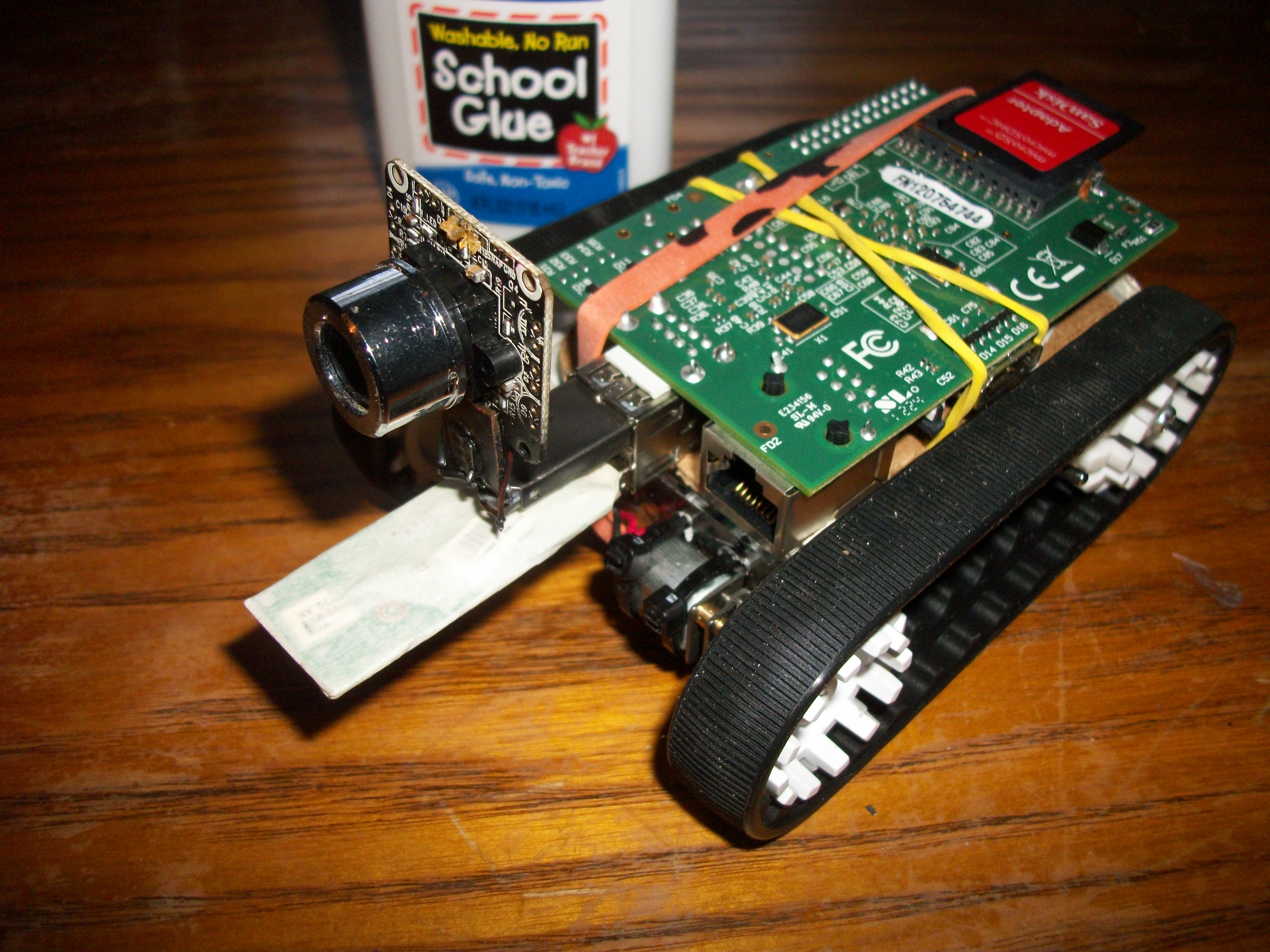
Hardware
I’m using a lm7805 that is being driven by two cr123 lithium batteries. I can drive around for about 30 minutes before my batteries die. It does not take long to recharge them and I have an extra pair that is always charging. The batteries themselves are very lightweight and are only about $1 each on ebay. There is a big cap on the 5v power side of the 7805 in case there is a dip in current during motor drive, this way the circuit does not loose power when we put a lot of current into the motors.
My motor drivers are TA7291S/SG because thats what I have around. I soldered them dead bug style to a female header. This allows me to have motor drivers and power circuitry stay with the body and simply plug into the pi gpio header.
I’m using Pololu 30T track set http://www.pololu.com/catalog/product/1416 and some micro motors I got off ebay a while ago. The case was built from plexiglass from a design I made years ago.
Pictures


Update Speed fps issues !
I was going crazy trying to figure out why if I have usb 2.0 which runs at “480 Mbit/s (effective throughput up to 35 MB/s or 280 Mbit/s)” why the hell does my framerate drop to almost nothing when I use 320×240. Then it occurred to me even though whats going to the webpage is pretty small since my camera does not have jpeg compression everything going through the usb port is raw, and the usb port is shared with the wifi. So, those two devices are quickly going to max out the bandwidth.
Just a quick math note, the raw data going though my port is
320x240x2= 153600 at 10fps = 1536000 which is 1.5MB/s ….
Ya I take all that back, the usb should not be the bottleneck. It might be the two devices on the same port. Just as a test I used a raw usbcam on my normal pc and was getting realtime at 640×480. So I dont know, I’ll try and test a cam that supports h.264 or mjpg streaming once I get one. For now looks like low resolution and 150Kbs will have to do. Maybe the “Raspberry PI CSI” camera will solve all of this ?
Raspberry Pi vs Small MCU type Solutions
I have known about the raspberry pi for quite some time. So why did I spend so much time working with embedded systems like pic and stm32 ? Initially I thought of the extremely low cost and power requirements for those devices. My initial estimates were for a controllable tracked video bot for as little as $25, which is still realistic.
I’m going to weigh the costs and benefits of each system and we can see they are different systems, kind of like comparing apples to oranges. So yes I think both systems are very desirable. The pi gets me where I want to be faster, and it can support ROS. To me ROS makes all the difference so I’m going down the Pi path for that reason. But I’m going to release all of my code for the stm and everything I have worked on so far in case someone else wants to still pursue the embedded path.
The last thing I completed was a phone controlled bot based off of the stm32f4 discovery board. I was using a bluetooth module and was getting about a 250×100 frame every 2 seconds on my phone. I have a full api thats easy to use and all of the source is open and free here. There are android and pure java clients that get the video feed. Even thought the HC-05 module boasts 1.3Mbps it also says 160Kbps which is the max speed I was able to push through it. If anyone figures out the actual max speed please let me know !
https://code.google.com/p/stm-phone-camera-bot/source/checkout
With all of this working at a frame every 2 seconds I still had in the back of my head that with jpeg that could be 1/16 compression giving me 8 frames per second. I was also planning to implement nordic rf 2401 which gives a possible 2 mbps which would greatly increase the frame rate. What I would end up with in the end would be pretty spectacular but it would not run ROS.
So lets compare everything.
Assuming !
Motor control circuit is the same
Power charge circuit is the same
And disregarding passive components as negligible
Plan A:
Stm32F4, Bluetooth module connect direct to telephone.
Difficulty to Implement: Moderate
Todo: Interface with Ov2460, more drivers for HC-05
Modular: Low
| Product | Cost | dBm | Range ft | Ram MB | Clock | Mbps | Volts | mA | Watts |
| STM32F407VET6 | 10.99 | 0.125 | 168 | 3.3 | 87 | 0.287 | |||
| HC-05 | 5.66 | 4 | 30 | 3.3 | 50 | 0.165 | |||
| OV2640 | 9.99 | 3.3 | 45 | 0.149 | |||||
| sum | 26.64 | 4 | 30 | 0.125 | 168 | 0 | 9.9 | 182 | 0.601 |
Plan B:
STM32F4 based, nordic chip. For this to work I would need to make a dongle board for converting the nordic input to usb. This would be very hard and possibly slow things down considerably, but at least I would need chips on both ends to control everything. I would use a lower cost stm32 for the Dongle end.
Development: Hard
Todo: dongle, spi nrf interface driver, camera driver
| Product | Cost | dBm | Range ft | Ram MB | Clock | Mbps | Volts | mA | Watts | ||
| STM32F407VET6 | 1 | 10.99 | 10.99 | 0.125 | 168 | 3.3 | 87 | 0.287 | |||
| STM32F051K8U6 | 1 | 3.17 | 3.17 | 0.0625 | 48 | 3.3 | 22 | 0.073 | |||
| OV2640 | 1 | 9.99 | 9.99 | 3.3 | 45 | 0.149 | |||||
| FTDI-FT230XS-R | 1 | 2.04 | 2.04 | 2 | 5.5 | 8.3 | 0.046 | ||||
| nrf2401AG | 2 | 4.2 | 8.4 | 1 | 3.6 | 18 | 0.065 | ||||
| 2.4Ghz Antenna | 2 | 3.25 | 6.5 | 984 | 0 | ||||||
| sum | 8 | 33.64 | 41.09 | 0 | 984 | 0.1875 | 216 | 1 | 19 | 180 | 0.619 |
Plan C:
Use a raspberry pi (Model A) and usb camera, stream over wifi. Of course there are obvious issues with this like how do I embedd a usb dongle or webcam into the final product. In a few units I can dismantle and solder but I would need a better solution for mass production. Also I will need to integrate a usb hub whereas in the other designs that was not nessisary.
Difficulty: done
Todo: Add configuration, Create Circuit board, Test
| Product | Cost | dBm | Range ft | Ram MB | Clock | Mbps | Volts | mA | Watts | ||
| rPi Model A | 1 | 35 | 35 | 256 | 700 | 5 | 500 | 2.5 | |||
| Logitec C200 | 1 | 3.3 | 3.3 | 5 | 200 | 1 | |||||
| RTL8188cus | 1 | 4.75 | 4.75 | -65 | 300 | 150 | 3.3 | 600 | 1.98 | ||
| 2.4Ghz Antenna | 1 | 3.25 | 3.25 | 0 | |||||||
| TUSB2046BIVFRG4 | 1 | 3.2 | 3.2 | 3.3 | 40 | 0.132 | |||||
| 8gb microsd | 1 | 5.95 | 5.95 | ||||||||
| sum | 6 | 55.45 | 55.45 | -65 | 300 | 256 | 700 | 150 | 16.6 | 1340 | 5.612 |
Summarizing and including the model B since model A does not always seem to be available.
| Product | Cost | Cost | dBm | Range ft | Ram MB | Clock | Mbps | Volts | mA | Watts | |
| STM BT | 0 | 26.64 | 4 | 30 | 0.125 | 168 | 0.16 | 9.9 | 182 | 0.601 | |
| STM NRF | 0 | 41.09 | 0 | 984 | 0.1875 | 216 | 1 | 19 | 180 | 0.619 | |
| RPI – A | 0 | 55.45 | -65 | 300 | 256 | 700 | 150 | 16.6 | 1340 | 5.612 | |
| RPI – B | 0 | 71.45 | -65 | 300 | 256 | 700 | 150 | 5 | 1540 | 7.7 |
The big things to note are 150Mbps(pi) vs 1Mbps(STM) and the mA 1.5A (Pi) vs .180A (STM). So all things the same the STM plan would last 8 times as long as the Pi on the same battery charge. For example I’m using two CR123 Rechargables at 800mAh in the pi that gives me 32 Minutes, the STM would last for 4.3 hours on the same two light batteries. However when we are pumping motors continually the amps used by the PI might not be so important. For example if our motors (fa-130 for example) use from 200 to 2.2A each then we round that to 2A we need a larger battery solution. The 150Mbps vs 1Mbps is a no brainier if you are trying to push any decent video size through the device.
At the cost of only $14 more it seems like the Pi is the clear way to continue. The stm plans would only support one set of per devices like cameras, wireless etc whereas the pi has tons of drivers and a huge list of already supported devices.
So with all that in mind I’m moving forward knowing that I will be pulling something like 3A and will need a large battery solution. Since the motors and several other parts of the circuit would be the same regardless of the “brain” then we can always go back. But with things like ROS and Ubuntu I dont think there is going to be any turning back. The most I might do is use my STM32 knowledge to integrate smart perphs into the pi.
How to Stream video from your Raspberry Pi and control GPIO
There are a plethora of different packages out there for streaming video. The one I found that is closest to real time is “mjpg_streamer” that does not mean its the best or that you cannot achieve better with another package, it just means this is the one that I got to work best so far.
To install follow the instructions here
http://www.tanzilli.com/video_streaming
If thats not enough info you can look here too
http://www.phillips321.co.uk/2012/11/05/raspberrypi-webcam-mjpg-stream-cctv/
The final command I used was a very low image size to give me about 10fps
mjpg_streamer -i "/usr/lib/input_uvc.so -d /dev/video0 -y -r 160x120 -f 10" -o "/usr/lib/output_http.so -p 8081 -w /home/pi/mjpg-streamer/mjpg-streamer/www/" -b
From there you can http into your pi on its ip at yourpiip:8081 and you should see pages to stream your video. The tricky thing that is not mentioned on those pages is the last -w argument is for the webpages which if you follow the instructions you delete. You should save those pages or when connecting you will get a “404 not found” because you pointed mjpg_streamer to host pages that dont exist. I have the full path in my argument as you see.
From there gpio was a snap I used WebIOPi you can find the instructions here
https://code.google.com/p/webiopi/wiki/INSTALL
and yes you can have them both running at once (camera gpio) as long as they are on different ports.
I installed both as a service so my pi starts right up and streams video and opens its gpio. So I hooked up some lights and put them in front of the camera. Now I can toggle them on and off from anywhere in the world (since I forwarded the pages) and see them.

The webiopi wont let me drive since I have to turn on two gpio at the same time to go forward or back, but it will be good for testing. Next I’m moving on to making my own javascript gpio control then I can connect it to the chassis and drive it around !
RaspBerry Pi, Goals
Though unfortunate events I burnt up my stm32f4 discovery, so I thought to myself now would be a good time to load up the raspberry pi and see what I could do with it.
I found an instructable with a link to Raspian with ROS built in. http://www.instructables.com/id/Raspberry-Pi-and-ROS-Robotic-Operating-System/step2/Writing-the-image-to-the-SD-card/
Then I found instructions on how to setup a wifi webcam that runs off solar batteries. This camera is hosted across the web in any browser. http://www.instructables.com/id/Raspberry-Pi-Completely-Wireless-IP-Camera-Solar/
To manipulate the gpio there are several different methods, there is a very exhaustive page here that shows how to do it in basically any language you want. Looks like pwm might be out of scope for the first run but controlling my already built motor drivers should be easy.http://elinux.org/Rpi_Low-level_peripherals
GOAL:
Putting this all together we should have what we wanted very quickly. A robot that can drive around using the wifi providing a video feed to a client. Looks like just by installing software the client will be a webpage. I will have to find a way to integrate the motor control and the video feed on the same page. If I could accomplish this then I would be far past where it has taken me about 2 years to get using MCU and integrating directly with the camera.
Once this works:
Daughter board
– Gets Power from batteries
– Charges Batteries
– Monitors Power
– Motor Drivers (4)
– Servo Drivers
– LED and Laser Connectors
– Camera Connector ?
Body
– Build a body that fits batteries, pi and daughterboard
– Construct and test
Other thoughts
I don’t know if we can take the schematic of the pi, strip out the stuff we dont want and include the stuff we do, such as wifi, motor drivers etc. If we could simply make our own version of the rPi that would be better than fitting a square peg in a hexagon hole.
There is tons of interest right now in the rPi, it is buzzing all over the internet and every Tom, Dick and Harry is making accessories for it. It will be nice to ride that wave instead of using MCUs that are less renown. I can say that if we make accessories they should cost less than the pi itself. If I make a full video bot package we should be able to keep the cost below $100.
Unpleasent Bluetooth Suprises
Using the bluetooth modules I have become pretty familiar with them. There are several different models out there but most of them are banging the BC417 core for bluetooth.
The idea was we could have speeds up to the at commands for baud which has a max of 1382400 baud. With that we could do 3.5 frames a second with raw at 251×100 at 2 bpp, of course in a perfect world with no overhead. Then I would move onto a camera that has built in jpeg compression and get a 1/16 compression ratio moving my fps to 56 fps at which time I could start to adjust for a bigger image and get closer to 20fps but with a larger image.
Wrong ! After setting the bluetooth to a higher baud 921600 I maxed out the kbps at 160 rx. This does not make any sense to me so I look at the modules specs and I see
Rate: Asynchronous: 2.1Mbps(Max) / 160 kbps.
There was another spec for synchronous but usart is async. I really dont know why these are written this way, maybe its 2.1Mbps upload and 160kbps down or maybe its 2.1Mbps on the usart side and 160kbps max on the bluetooth side or maybe its simply showing that the max is 2.1Mbps and we need at least 160kbps for the other side.
So I dove deeper into the bc417 datasheet it shows the uart can communicate as fast as 2764800, but if you look at the rfcomm section 9.2.1 you see it has a 350kbps max data rate. I have no idea how any of these chips could have data coming in at a huge rate and going out at a much slower one, maybe I would see buffer overflow if I pushed to much. Actually I think I did at about 700+ bytes.
Bottom line max kbps is 350 for what we are using, all I can seem to get out of it is 160kbps which may be a limitation of how they implemented the host mcu on the bluetooth module, but the datasheet for the bt module is confusing (to me). So even if we could get 350kbps that would be only .87 fps raw (a frame every 1.14 sec) or possibly ~13 fps with jpeg compression.
What I have working now is 160kbps at a decent range. That gives me .39fps or a frame every 2.56 sec which is ~5fps with compression. If I put my api on the computer and use a serial adapter I can get 921600 baud (max of prolific usb converter) and see 2fps. 2fps is much better than a frame every 2.56 sec, and it still sucks !
Options ?
I could use the nordic rf2401 chips and implement a dongle as I had in mind before. I know android devices are getting better at using usb converters and such. This would give me decent performance.
Rosberry pi with wifi.